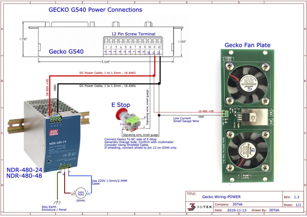

Keep these as short as feasible (less than 12" if possible), as the G540 can be finicky about inductance if they get too long. Next up, you'll need to connect DC power to the G540 using your 18 AWG or larger cable. Green is ground, black is hot (or "line") and white is neutral. Next, locate the AC input terminals on the power supply. Strip the ends off of the wires, and crimp on ring or spade terminals if desired. Almost any cord will suffice, as the G540 does not draw excessive amounts of current. Start by cutting the female end off of an AC power cord.
#Gecko g540 manual professional#
For a professional install, ferrules and crimps can be used on your wire ends, but this isn't strictly necessary. Next you will want to make sure you have a few tools handy - a Philips head screwdriver for the power supply, a small Philips for the G540 connections, and a set of wire strippers will be needed.
#Gecko g540 manual how to#
We'll show you how to hook the system up both jumpered and with an e-stop. It's also recommended to have an emergency stop, but if you don't have one, you can jumper this out initially while you're testing motors off of your machine.

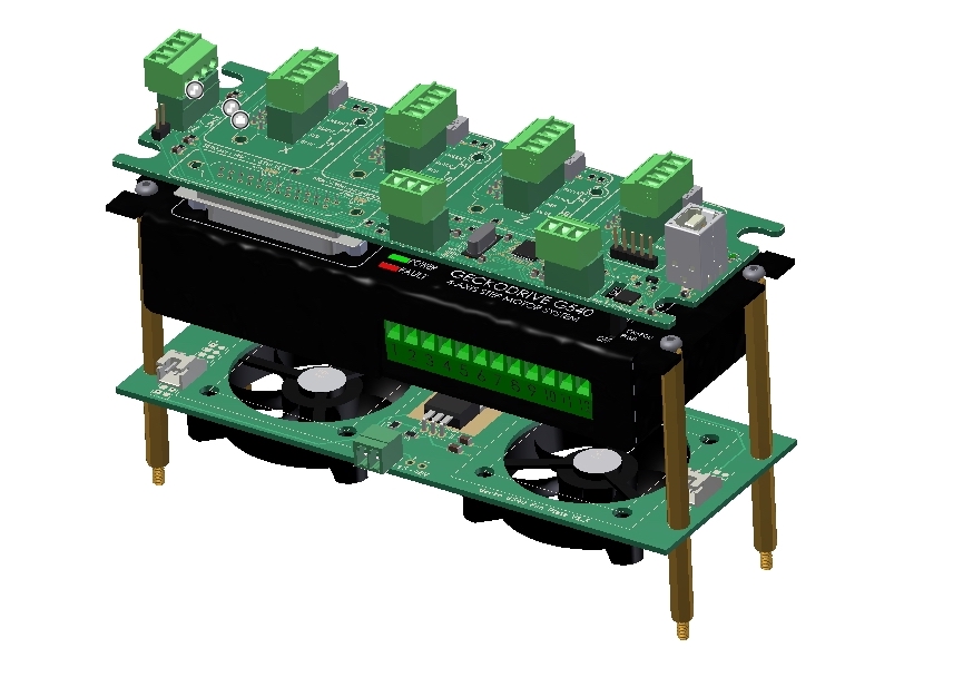
Note, this guide shows a 7.3A power supply for a 3 axis system, but the process is the same for the 4 axis system, you'll just be using the larger 12.5A supply. You'll need an AC power cable, a DC power supply, some 18 AWG or larger wire to connect the power supply, a motor, a motor cable, a parallel port cable, and of course a G540. The first step is to insure you have all of the parts needed - these are shown below. Read on to see how it's done using our components. We created this handy step by step guide to help get you going with our products.

While the G540 makes hooking up motors and getting them working a breeze, it can still be a bit daunting for those new to electronics and CNC.


 0 kommentar(er)
